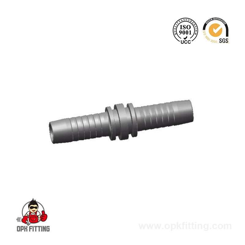
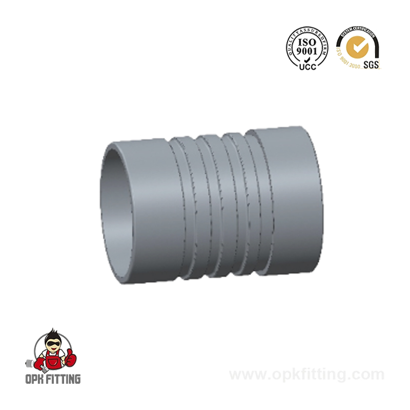
Hydraulic hose fittings are the mechanical connectors that join hydraulic hoses to pumps, cylinders, valves, and other system components, forming sealed, pressure-rated fluid pathways in hydraulic systems. Choosing the correct hydraulic fitting is not a minor detail — a mismatched thread type, wrong pressure rating, or incompatible material can result in system leaks, pressure failures, or catastrophic hose blowouts. For engineers, maintenance technicians, and procurement professionals, understanding the full landscape of hydraulic connectors, thread standards, and assembly practices is essential to building reliable, long-service hydraulic systems.
This guide covers everything from thread standards (JIC, BSP, NPT) and fitting materials to hydraulic hose assembly best practices and high-pressure hydraulic fittings selection — giving you the knowledge to make confident, application-specific decisions.
What Are Hydraulic Hose Fittings and Why Do They Matter?
Hydraulic hose fittings serve as the critical interface between flexible hose sections and the rigid ports of hydraulic equipment. They must simultaneously provide a leak-free seal under dynamic pressure pulses, resist vibration-induced loosening, withstand the chemical properties of hydraulic fluid, and survive the temperature extremes of the operating environment. In heavy-duty industrial applications, hydraulic systems commonly operate at pressures between 200 and 700 bar, with high-pressure hydraulic fittings in specialized circuits reaching up to 1,000 bar or more.
Unlike standard pipe fittings used in plumbing, hydraulic fittings must maintain integrity through repeated pressure cycles, thermal expansion, and mechanical vibration — conditions that would quickly loosen or degrade connections designed for static service. The consequence of fitting failure in a hydraulic system extends far beyond a simple leak: hydraulic fluid under pressure can cause injection injuries, fire hazards (many hydraulic fluids are flammable), equipment damage, and costly unplanned downtime.
Primary Functions of Hydraulic Fittings
Fluid routing: Directing flow between components via straight, elbow (45° and 90°), tee, and cross configurations.
Pressure containment: Maintaining a sealed fluid boundary at operating and surge pressures without deformation or leakage.
System adaptability: Connecting components with different thread standards, port sizes, or connection types via hydraulic adapters.
Vibration management: Allowing controlled movement of hose assemblies to prevent stress concentration at rigid connection points.
Material compatibility: Ensuring that fitting materials are chemically compatible with the hydraulic fluid, operating temperature, and external environment.
Major Hydraulic Fitting Thread Standards: JIC, BSP, NPT and More
Thread standard is the most common source of confusion when sourcing hydraulic fittings. Several incompatible thread systems are in widespread global use, and many look similar enough that mis-identification leads to cross-threading, damaged ports, or false-seal assemblies that fail under pressure. The four dominant standards are JIC fittings, BSP fittings, NPT hydraulic fittings, and metric (DIN) fittings.
JIC fittings and SAE O-ring face seal fittings both use UN/UNF straight threads and can look identical externally. The difference is in the sealing surface: JIC uses a 37° internal cone, while ORFS uses a flat face with an O-ring groove. BSP parallel (BSPP) and BSP tapered (BSPT) share the same thread pitch and diameter but differ in taper — BSPT threads will not seal reliably in a BSPP port without additional sealing. A thread gauge and pitch comparison are the reliable tools for definitive identification.
Global Market Share by Hydraulic Fitting Thread Standard (Estimated %)
BSP fittings collectively represent the largest global share at approximately 35%, reflecting their widespread adoption across European and Asian industrial markets and the extensive export-oriented manufacturing in these regions. JIC 37° flare fittings hold a strong 28% share driven by North American mobile equipment and the aviation sector. DIN metric connectors, popular in German-engineered machinery exported worldwide, account for roughly 18% of the market. Understanding this distribution helps procurement teams anticipate which thread standards will be most available from local hydraulic hose suppliers and hydraulic fitting manufacturers.
Types of Hydraulic Hose Fittings by Connection Geometry
Beyond thread standards, hydraulic fittings are classified by their geometric configuration — the physical shape that determines how the hose routes through a system. Selecting the correct elbow angle or configuration affects not just assembly convenience but also system performance, as sharp bends and stress concentrations near fittings are a leading cause of hose fatigue failure.
Straight fittings: The simplest and most common type. Used when the hose runs parallel to the port axis. Minimal flow resistance, easiest to assemble and service.
45° elbow fittings: Used when a moderate direction change is needed without a tight-radius hose bend. Common in machine tool and agricultural equipment applications.
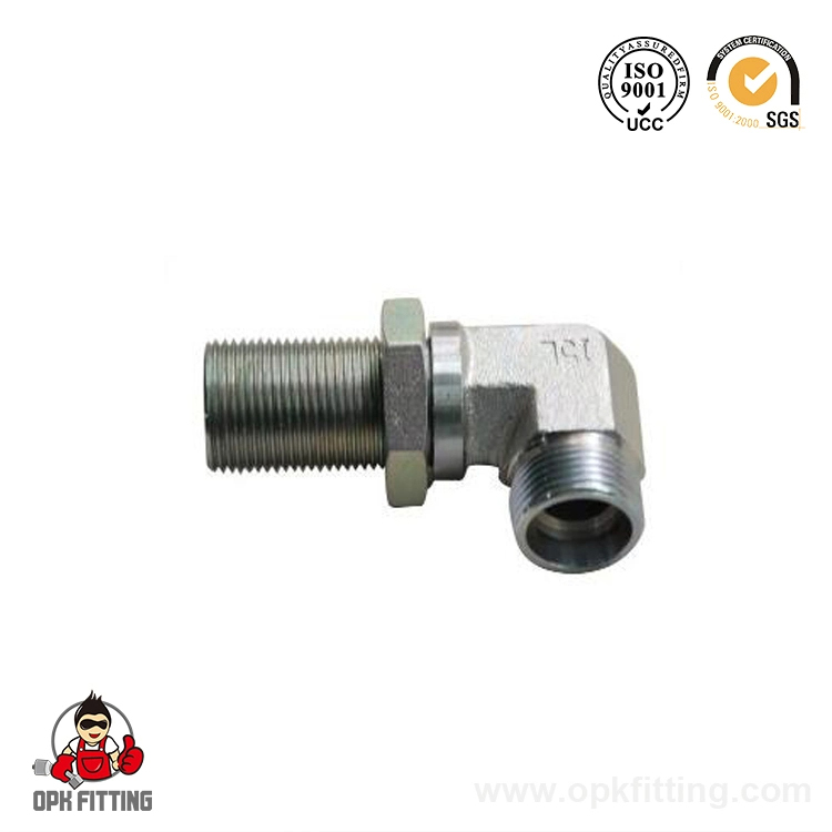
90° elbow fittings: The most widely used elbow type. Allows a hose to exit a port perpendicular to the equipment face, saving space and avoiding sharp hose bends. Available in fixed and swivel configurations.
Swivel fittings: Feature a rotating outer nut that allows the hose to be positioned without twisting during tightening. Critical for preventing hose twist stress, which reduces hose fatigue life by up to 70%.
Banjo fittings: A hollow bolt with a radial port, allowing fluid to enter from the side while the bolt passes through the component. Common in compact hydraulic circuits and braking systems.
Tee and cross fittings: Allow a single line to split into two or three branches. Used in manifold-style circuits where multiple actuators share a single supply line.
Reducer fittings: Connect hoses or pipes of different bore sizes. Common in transition zones between high-pressure small-bore supply lines and larger return lines.
Common Hydraulic Fitting Configurations (Schematic View)
The diagram illustrates five fundamental hydraulic fitting configurations encountered in typical system design. Straight fittings offer the lowest flow resistance and are preferred wherever the hose routing allows. Elbow fittings — particularly 90° types — are the most commonly specified fittings in compact machine designs where ports face awkward directions relative to the hose routing path. Tee fittings introduce flow splits that require careful velocity and pressure drop analysis to ensure equal distribution to downstream actuators, while banjo fittings solve the geometric challenge of connecting to ports in tight, enclosed spaces.
Hydraulic Fitting Materials: Carbon Steel, Stainless Steel, and Brass
Material selection for hydraulic fittings directly affects corrosion resistance, pressure rating, weight, compatibility with hydraulic fluid, and cost. The three primary material groups used by hydraulic fitting manufacturers are carbon steel (with plating), stainless steel, and brass — each with distinct strengths and limitations.
Carbon Steel (Zinc or Nickel Plated)
Carbon steel is the default material for the majority of industrial hydraulic fittings due to its high strength, ease of machining, and relatively low cost. Carbon steel fittings are typically zinc-plated or nickel-plated to provide surface corrosion protection for indoor and moderate outdoor environments. They are suitable for petroleum-based and synthetic hydraulic fluids, and can handle working pressures from 400 to 700 bar in high-pressure configurations. The limitation is corrosion resistance — in aggressive environments involving saltwater, acids, or prolonged outdoor exposure without surface protection, plated carbon steel will corrode.
Stainless Steel Hydraulic Fittings
Stainless steel hydraulic fittings — primarily 316L grade — are specified for marine environments, food and beverage processing, pharmaceutical systems, chemical plant hydraulics, and any application where long-term corrosion resistance is more important than minimizing material cost. SS316L offers excellent resistance to chlorides and most hydraulic fluids, and maintains structural integrity across a wide temperature range from -196°C cryogenic service to +450°C. The trade-off is that stainless steel is harder to machine than carbon steel, leading to higher production costs and longer lead times from most hydraulic fitting manufacturers.
Brass Hydraulic Fittings
Brass fittings are used in lower-pressure hydraulic applications (typically below 200 bar), instrument tubing, and water-glycol hydraulic fluid systems where zinc-contamination from carbon steel is a concern. Brass offers good machinability and natural corrosion resistance but has lower tensile strength than steel and is susceptible to stress corrosion cracking in the presence of ammonia or amines.
Hydraulic Fitting Material Performance Radar (Score 0–10)
The radar chart compares three primary hydraulic fitting materials across six performance dimensions. Carbon steel (dark red) dominates in pressure rating, machinability, cost efficiency, and strength-to-weight ratio — the four attributes that drive its dominant market position in industrial hydraulics. Stainless steel (medium red dashed) leads strongly in corrosion resistance and temperature range, making it the correct choice for demanding environments despite higher material and processing costs. Brass (light fill) occupies a middle ground in corrosion resistance and machinability but falls short on pressure rating, limiting its use to lower-pressure hydraulic circuits and instrumentation systems.
High Pressure Hydraulic Fittings: Design Considerations Above 400 Bar
High pressure hydraulic fittings — generally defined as those rated above 400 bar (5,800 psi) — require fundamentally different design approaches compared to standard industrial hydraulic connectors. At extreme pressures, material fatigue, thread shear strength, seal extrusion, and stress concentration at geometry transitions all become critical failure modes that standard fittings are not designed to address.
The predominant connection system for ultra-high-pressure applications (700–1,000+ bar) is the cone-and-thread fitting (also known as the Autoclave or HP cone-type connection), which relies on metal-to-metal sealing between a hardened internal cone and a mating seat machined directly into the fitting body. This eliminates elastomeric seals entirely — a necessity since O-rings and polymeric seals extrude through clearances at pressures above approximately 400–500 bar.
Critical Design Parameters for High-Pressure Hydraulic Fittings
Wall thickness to bore ratio: High-pressure fittings use significantly thicker walls relative to bore diameter. A working pressure of 700 bar typically requires a wall thickness 3–4 times the bore radius.
Thread engagement length: Longer thread engagement distributes axial load over more threads, reducing the peak stress per thread root — critical for preventing fatigue cracking under pressure cycling.
Autofrettage: Many high-pressure fitting bodies undergo autofrettage — deliberate over-pressurization during manufacturing that induces beneficial compressive residual stresses in the bore wall, significantly extending fatigue life.
Material grade: High-pressure fittings typically use high-alloy steel (e.g., 4140 chromoly or 17-4PH stainless) with heat treatment to achieve tensile strengths of 900–1,200 MPa.
Surface finish: Bore and sealing surface finish is critical — Ra 0.4 µm or better is commonly specified to prevent leak paths and stress risers at the sealing interface.
Required Wall Thickness Ratio vs. Working Pressure for Carbon Steel Fittings
This line chart illustrates how wall thickness requirements scale nonlinearly with operating pressure. At 100 bar, a wall/bore ratio of approximately 1.2 is sufficient for carbon steel fittings with standard safety factors. By 700 bar, this ratio rises to 4.0, and approaches 5.0 at 1,000 bar — resulting in fittings that are physically much heavier and require precision machining to achieve the necessary surface finishes. The orange dashed line marks the 400–500 bar threshold where standard elastomeric seals begin to fail and metal-to-metal or cone sealing designs become necessary for reliable hydraulic hose assembly performance.
Hydraulic Hose Assembly: Crimp vs Reusable Fittings
The method by which a hydraulic fitting attaches to the hose end is as important as the fitting thread standard itself. Two fundamentally different approaches are used: crimped hose assembly (factory or field crimped) and reusable field-attachable fittings. Each has specific advantages, limitations, and appropriate use cases.
Crimped Hydraulic Hose Assemblies
Crimped assemblies use a hydraulic crimping machine to permanently compress a ferrule onto the hose end and fitting stem. The crimp creates a mechanically interlocked, leak-free connection that — when performed correctly with matched hose and fitting from the same hydraulic hose supplier system — achieves the full rated working pressure of the hose. Crimped assemblies account for approximately 85% of all hydraulic hose assembly production globally, driven by their consistent quality, wide pressure range capability, and suitability for automated production.
Reusable Field-Attachable Fittings
Reusable hydraulic fittings consist of a socket (outer shell) and nipple (inner stem) that are threaded together around the hose end without specialized crimping equipment. They are particularly valuable in remote field locations, mining sites, or marine vessels where carrying a crimping machine is impractical and hose failures must be repaired quickly with hand tools. The trade-off is slightly lower pressure rating consistency compared to properly crimped assemblies, and they require more careful assembly to achieve rated performance. Reusable fittings are generally rated to the same nominal pressures as crimped equivalents but require strict adherence to assembly torque specifications.
Crimped vs Reusable Hydraulic Hose Assembly Usage by Industry (%)
This grouped column chart reveals how assembly method preference shifts significantly by industry sector. Manufacturing environments overwhelmingly prefer crimped assemblies (92%) because controlled factory or workshop crimping with calibrated equipment produces the most consistent quality. Mining and marine sectors show a substantially higher proportion of reusable fittings — 40% and 35% respectively — reflecting the practical reality that these environments are remote, and field repair capability is essential when a hydraulic hose failure occurs on a machine that cannot easily be transported to a workshop. Understanding this balance helps hydraulic hose suppliers tailor their product recommendations to each industry's operational context.
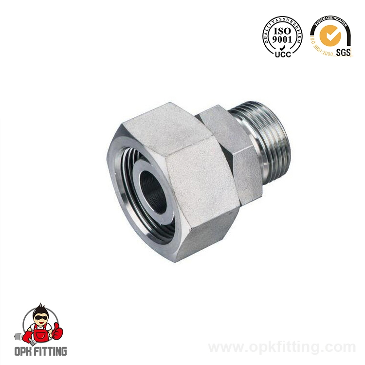
Hydraulic adapters are fittings with two different thread types on opposite ends, allowing connection between components that use different port standards. In real-world hydraulic systems — particularly those assembled from components sourced globally — it is very common to encounter a BSP-ported pump connected to a JIC hose assembly, or an NPT hydraulic fitting manifold connected to metric DIN hose ends. Adapters solve this compatibility challenge without requiring replacement of major system components.
Common hydraulic adapters include BSP to JIC, NPT to BSP, JIC to metric, and BSP to SAE O-ring face seal combinations. When using adapters, it is important to recognize that the pressure rating of the adapter assembly is limited by the lower-rated thread standard in the connection — for example, an NPT-to-JIC adapter used in a 300 bar system must be rated for 300 bar on both ends.
Reputable hydraulic fitting manufacturers offer complete adapter catalogs that cover the most common cross-standard combinations in standard carbon steel and stainless steel hydraulic fittings, and can supply ODM/OEM custom adapters for unusual port geometry combinations specific to particular machine designs.
Adapter Type
End 1
End 2
Typical Max Pressure
Common Use Case
BSP to JIC
BSPP male/female
JIC 37° male/female
420 bar
EU equipment with US hose assemblies
NPT to BSP
NPT male/female
BSPP male/female
280 bar
North American components in global systems
JIC to DIN Metric
JIC 37° male
DIN metric male
400 bar
Mobile equipment with German-spec valves
BSP to SAE ORFS
BSPP male
SAE ORFS male/female
420 bar
High-pressure European to North American systems
Table 2: Common Hydraulic Adapter Combinations — Thread Standards, Pressure Ratings, and Applications
How to Select the Right Hydraulic Hose Fitting: A Practical Framework
Selecting the correct hydraulic fitting requires evaluating seven key parameters — often summarized as the STAMPED method (Size, Temperature, Application, Material/Media, Pressure, Ends, Delivery). Working through these systematically eliminates the most common specification errors.
Size: Determine the correct hose inner diameter (bore) and fitting connection size. The bore must match the system flow rate requirements — undersizing creates excessive pressure drop; oversizing wastes material and increases cost.
Temperature: Identify both the fluid temperature range and the ambient temperature. High temperatures require specific seal materials (EPDM, FKM) and may reduce the pressure rating of the hose assembly.
Application: Define the mechanical environment — static or dynamic flexing, vibration level, abrasion exposure, and whether the hose will be routed through restricted spaces requiring specific elbow configurations.
Material/Media: Confirm the hydraulic fluid type — petroleum-based, water-glycol, synthetic ester, phosphate ester — and ensure fitting and seal materials are chemically compatible. Some fluids attack zinc plating; others are incompatible with standard NBR seals.
Pressure: Specify the maximum working pressure AND the surge/peak pressure. Hydraulic systems routinely experience pressure spikes 2–3× the nominal working pressure during valve actuation. The fitting and hose assembly must be rated for these peaks.
Ends: Identify the port standards on both ends of the hose assembly. If they differ, specify the required hydraulic adapters. Confirm whether swivel ends are needed to prevent hose twist during installation.
Delivery: Consider assembly length tolerances, required certifications (ISO, SAE, EN), marking requirements, and delivery lead time when sourcing from a hydraulic hose supplier or hydraulic fitting manufacturer.
Root Causes of Hydraulic Hose Assembly Failure (% of Field Reports)
This breakdown of hydraulic hose assembly failure causes reveals a striking insight: the two largest contributors — wrong specification (30%) and hose twist or improper bend radius (22%) — are entirely preventable through correct product selection and installation practice. Together they account for over half of all field failures, none of which are due to product defects. Contamination (18%) and fitting loosening (15%) are the next most significant categories, both addressable through proper filtration practices and correct torque application during installation. This data underscores why systematic specification using the STAMPED method and sourcing from knowledgeable hydraulic fitting manufacturers substantially reduces lifetime maintenance costs.
Industries Served by Hydraulic Hose and Fitting Systems
The range of industries that depend on hydraulic hose assemblies and fittings is broad, reflecting the fundamental role of hydraulic power transmission in modern industrial and mobile equipment. Key sectors include:
Construction and earthmoving: Excavators, bulldozers, cranes, and concrete pumps rely on high-pressure hydraulic circuits with hundreds of hose assemblies per machine. Pressure ratings of 350–420 bar are typical.
Metallurgy and steel production: Rolling mills, forging presses, and continuous casting equipment operate at up to 700 bar, with high-temperature environments that demand stainless steel hydraulic fittings and FKM-sealed assemblies.
Petroleum and petrochemical: Offshore drilling equipment, subsea BOP systems, and refinery control systems require hydraulic connectors rated for high pressures and corrosive environments, often with fire-resistant hydraulic fluids.
Agriculture: Tractors, combine harvesters, and irrigation systems use medium-pressure hydraulic circuits (140–280 bar) with long hose assemblies routed through the machine frame.
Aerospace and defense: Aircraft hydraulic systems operate at 207–350 bar with strict weight, cleanliness, and certification requirements. JIC 37° and AN fittings dominate this sector.
Food and pharmaceutical: Sanitary hydraulic systems use stainless steel hydraulic fittings, food-grade hydraulic fluids, and PTFE-lined hose assemblies to prevent contamination of the product stream.
Marine and shipbuilding: Deck machinery, steering systems, and hatch cover actuators operate in salt-air environments requiring stainless steel or heavily coated carbon steel hydraulic fittings.
Frequently Asked Questions About Hydraulic Hose Fittings
Q1: What is the difference between JIC and BSP hydraulic fittings?
JIC fittings use UN/UNF straight threads with a 37° internal flare cone for metal-to-metal sealing, and are the standard across North American mobile equipment and the aerospace sector. BSP fittings (both BSPP parallel and BSPT tapered) use British Standard Whitworth thread form and seal either via a bonded seal washer (BSPP) or thread taper engagement (BSPT). The two systems are not interchangeable — attempting to join JIC and BSP threads will result in cross-threading or a false seal that fails under pressure. Always identify the thread standard before replacing or assembling fittings.
Q2: How do I know what pressure rating my hydraulic fitting needs?
The fitting pressure rating must equal or exceed the maximum surge pressure in the hydraulic circuit — not just the nominal working pressure. Hydraulic systems commonly produce pressure spikes 2 to 3 times the normal operating pressure during valve actuation or sudden load reversal. As a practical rule, select fittings with a rated working pressure at least 25% above the highest normal system pressure, and verify the assembly against any known surge conditions. For OEM or custom system design, consult with a hydraulic fitting manufacturer who can provide pressure calculation support based on your specific circuit parameters.
Q3: Can I use NPT fittings in a hydraulic system?
NPT (National Pipe Tapered) fittings can be used in hydraulic systems, but with important limitations. NPT threads rely on thread engagement and PTFE thread tape for sealing, making them suitable for low-to-medium pressure applications (typically below 210 bar). For higher pressures or dynamic applications with vibration, NPTF (National Pipe Tapered Fuel) — also known as Dryseal — provides more reliable sealing through controlled thread interference. However, most modern hydraulic system designs have moved away from NPT fittings in favor of O-ring face seal or JIC connections for higher reliability above 200 bar.
Q4: When should I use stainless steel hydraulic fittings instead of carbon steel?
Stainless steel hydraulic fittings are the right choice in four main situations: marine and offshore environments where salt air or seawater contact will cause rapid corrosion of plated carbon steel; food, beverage, and pharmaceutical hydraulic circuits where contamination from corrosion products is unacceptable; chemical processing systems where the external environment involves corrosive vapors or wash-down with harsh cleaning agents; and high-temperature applications where carbon steel plating would degrade. For standard indoor industrial hydraulics with petroleum-based fluids, properly plated carbon steel provides adequate service life at lower cost.
Q5: What causes hydraulic hose fittings to leak and how can it be prevented?
The most common causes of hydraulic fitting leaks are under-torquing (insufficient thread engagement), over-torquing (damaged sealing surfaces or deformed O-rings), contaminated sealing surfaces (debris between the cone face and seat), and wrong thread or seal material for the application. Prevention starts with verifying the thread standard before assembly, cleaning all sealing surfaces, applying the manufacturer's specified torque (not "tight by feel"), and using the correct seal material for the fluid and temperature. For O-ring face seal connections, inspect and replace the O-ring at each assembly rather than reusing potentially deformed seals.
Q6: What is the benefit of ODM/OEM hydraulic fitting customization?
ODM/OEM customization from a hydraulic fitting manufacturer allows engineers to specify fittings that exactly match their system's port geometry, material requirements, pressure ratings, and marking or certification needs — rather than adapting their design around catalogue standard parts. This is particularly valuable in high-volume production equipment where non-standard port configurations or compact packaging requirements make off-the-shelf fittings impractical, and in regulated industries (aerospace, medical, food processing) where specific material certifications or traceability documentation are mandatory. Custom hydraulic adapters and hose assemblies can also reduce the total part count in a system by combining multiple standard components into a single precision-machined fitting.
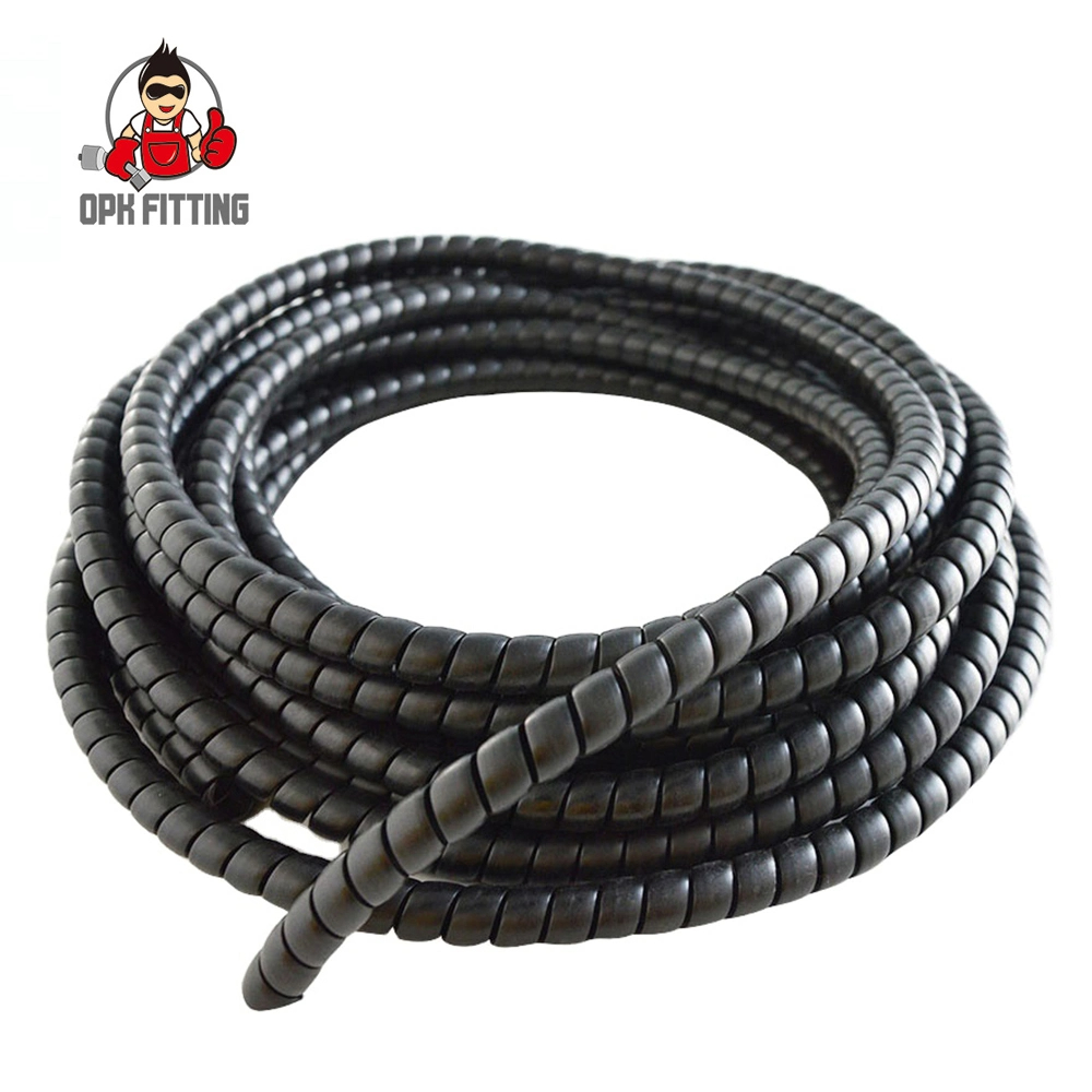
PRODUCT NAME: Spiral Protective Sleeve PP plastic hose guard for hydraulic hoseRecommended For: The use of Spiral Guard Wrap is an economical and conv...