


10511-RW Metric Male 24° Cone Seat L.T.
Cat:One Piece Hose Fitting For OPK Standard
1. Raw Material: Carbon Steel & Stainless Steel available2. Standard Plating: Trivalent Zinc Plating ( Cr3 / Chrome Free ), Silver & Yellow3. ...
See DetailsContent
Hydraulic systems are among the most powerful and reliable force-transmission technologies in industrial and mobile equipment — yet they are also responsible for a significant share of serious workplace injuries every year. Hydraulic fluid injection injuries, burst hose incidents, and high-pressure leaks account for thousands of lost-time accidents annually across construction, agriculture, manufacturing, and marine industries. The good news is that the vast majority of these incidents are preventable when operators follow proven safety practices.
This article delivers ten actionable hydraulic safety tips, grounded in real-world data and engineering principles. Whether you work with excavator hydraulic hose assemblies on a job site or manage industrial hydraulic hose networks in a production facility, these guidelines apply directly to your daily operations. Read the summary table first for a fast overview, then use the detailed sections to build or refresh your safety programme.
| # | Safety Tip | Primary Risk Addressed | Priority Level |
|---|---|---|---|
| 1 | Depressurise before any maintenance | Fluid injection injury | Critical |
| 2 | Inspect hoses and fittings regularly | Burst hose, fire, contamination | Critical |
| 3 | Use correct hose rating and routing | Premature failure, abrasion | High |
| 4 | Never use bare hands to detect leaks | Fluid injection, skin penetration | Critical |
| 5 | Match fittings to hose specification | Blow-off, leakage | Critical |
| 6 | Wear appropriate PPE | Eye and skin injury | High |
| 7 | Respect minimum bend radius | Internal tube collapse, failure | High |
| 8 | Monitor system pressure continuously | Over-pressure, component failure | High |
| 9 | Use proper crimping tools and technique | Fitting blow-off, leakage | High |
| 10 | Follow replacement intervals, not appearance | Hidden internal degradation | High |
The single most important hydraulic safety rule is to fully depressurise the system before disconnecting any hydraulic hose, fitting, or component. Hydraulic systems typically operate at pressures between 200 and 400 bar (approximately 3,000–6,000 psi). At these pressures, residual fluid in an apparently idle circuit can be ejected at velocities exceeding 400 metres per second if a connector is loosened without prior pressure release. This is the mechanism behind hydraulic fluid injection injuries — one of the most medically serious injury types in industrial maintenance, because the wound entry point may appear superficially minor while the internal tissue damage is severe.
To depressurise correctly, shut down the prime mover (engine or electric motor), cycle all control valves through their full range of motion to release trapped pressure in actuator circuits, and confirm zero pressure on the system gauge before touching any hydraulic hose fittings or connectors. Note that some circuits incorporate accumulators that store pressurised fluid even after the machine is switched off — these must be isolated and discharged separately according to the manufacturer's procedure.
In excavator hydraulic hose maintenance, it is also critical to lower all implements to the ground and block any suspended loads before commencing work on the hydraulic circuit. Gravity-loaded cylinders can create back-pressure that persists after engine shutdown and is frequently overlooked by inexperienced technicians.
Scheduled inspection is the backbone of hydraulic safety programmes. Industrial hydraulic hose assemblies degrade over time through a combination of internal abrasion from fluid particles, external abrasion from contact with machine surfaces, thermal cycling, UV exposure, and chemical attack from incompatible fluids. Many failures are predictable and preventable with a structured visual and tactile inspection protocol.
During each inspection, look for the following warning signs across the full length of every hydraulic hose assembly:
Industry guidance generally recommends visual inspection every 250 operating hours for high-cycle applications, and a comprehensive inspection including pressure testing annually or at each major service interval. Any hose that shows one or more of the above defects should be replaced immediately — not tagged for "monitor and replace next service." The cost of an unscheduled hose failure, including downtime, cleanup, and potential injury, far outweighs the cost of a proactive replacement.
The chart above illustrates that external abrasion is the leading cause of hydraulic hose failure, accounting for 40% of field cases. This highlights the importance of using protective sleeving, hose clamps, and correct routing to prevent hose-to-machine contact. Improper routing and excessive bending together account for a further 30%, underscoring that installation quality is as critical as material quality. Fitting and crimp failures — many of which are caused by using non-matched hydraulic crimp fittings or incorrect crimping tool settings — represent 20% of cases and are entirely preventable with the right tooling and specification practices. Fluid contamination, at 10%, is a silent degrader that shortens hose life from the inside out through abrasive particle damage to the inner tube.
Selecting the right high pressure hydraulic hose for each circuit position is not a matter of picking the highest available rating — it is about matching the hose specification precisely to the operating conditions of that specific circuit. Each hydraulic circuit has a defined maximum working pressure (MWP), but also experiences pressure surges (transient spikes) during valve actuation, cylinder end-of-stroke events, and system start-up. These surges can reach two to three times the steady-state working pressure and must be within the hose's rated impulse performance envelope.
Common hose standards such as SAE J517, EN 853, and EN 857 define pressure ratings, impulse cycle performance, and construction specifications for wire-braided and wire-spiral industrial hydraulic hose. A four-wire spiral hose (equivalent to SAE 100R13 or EN 856 4SP) is appropriate for high-pressure, high-impulse circuits such as those found in mobile hydraulic cylinders and steering systems, while a two-wire braid hose (SAE 100R2 / EN 853 2SN) is sufficient for medium-pressure return and drain lines.
Routing is equally critical. A correctly specified hose that is routed too close to the exhaust manifold, over a sharp metal edge, or under a rubber-track assembly will fail prematurely regardless of its pressure rating. General routing rules include: maintain a minimum clearance of 25 mm from hot surfaces without thermal shielding, avoid contact with moving parts, use clamps at intervals no greater than 500 mm for unsupported horizontal runs, and ensure no hose is under axial tension when the system is pressurised.
The column chart above shows the maximum working pressure ratings of common high pressure hydraulic hose constructions at DN12 bore. The 4SH/R15 four-spiral construction leads with up to 420 bar working pressure, making it the standard choice for heavy mobile equipment such as excavators, bulldozers, and mining machinery where both pressure and impulse demands are extreme. The single-wire braid 1SN construction, rated at 160 bar, is appropriate for low-pressure pilot and return lines only. Selecting a hose construction one tier below the circuit requirement — a common procurement shortcut — significantly increases the probability of early failure under impulse loading conditions, even if the hose never exceeds its steady-state rated pressure during normal operation.
Hydraulic fluid injection injury is classified as a medical emergency because the entry wound — typically a small pinhole — masks the true extent of internal tissue damage. A hydraulic hose pinhole leak at 300 bar produces a fluid jet with sufficient velocity and pressure to penetrate skin, fat, and muscle, injecting hydraulic oil (or biodegradable ester fluid) deep into tissue. The surrounding tissue responds with rapid inflammatory necrosis, and without surgical debridement within hours, the injury can result in permanent disability or amputation.
The correct method for locating a suspected hydraulic leak is to use a piece of cardboard or paper moved slowly along the hose and fitting surface while wearing safety glasses. The fluid jet will leave a wet mark on the paper, indicating the leak location without any skin contact. Fluorescent dye kits, which introduce a UV-visible tracer into the hydraulic fluid, are also widely used for locating seepage-type leaks at fittings, manifold faces, and cylinder rod seals without the need to touch pressurised components. These dye kits are compatible with most petroleum-based and biodegradable hydraulic fluids and do not affect fluid performance at recommended dosage levels.
If a hydraulic fluid injection injury does occur, the affected person must be taken to an emergency department immediately and the treating physician must be informed that the wound involved hydraulic fluid injection — not a simple cut or puncture. Treatment must be surgical, not conservative, and time from injury to debridement is the primary determinant of outcome.
Hydraulic hose fittings are engineered as a system with the hose body they connect to. A fitting designed for one hose construction — with a specific insert diameter, ferrule wall thickness, and crimp geometry — will not perform reliably when fitted to a different hose brand or construction, even if the nominal bore size appears identical. Mismatched assemblies may appear leak-free at low pressure but fail catastrophically when subjected to full working pressure or impulse cycling.
The key parameters that must match between a hydraulic hose connector assembly and its host hose are: bore size (ID), hose outside diameter (OD) tolerance band, inner tube material compatibility, and pressure rating. Hydraulic crimp fittings additionally require the correct crimp die set and target crimp diameter for each specific fitting-hose combination — these specifications are published in crimp charts by fitting manufacturers and must be followed precisely. Over-crimping collapses the inner tube and restricts flow; under-crimping leaves the fitting unsecured and vulnerable to blow-off under pressure.
For thread end connections, it is equally important to match thread type correctly. BSP (British Standard Pipe), NPT (National Pipe Thread), JIC 37-degree flare, ORFS (O-ring face seal), and SAE Code 61/62 flange connections are not interchangeable despite some superficial dimensional similarities. A BSP male fitted to an NPT female port may appear to tighten, but will leak under pressure because the thread form and sealing mechanism are different.
| Thread/End Type | Sealing Method | Max Pressure Range | Common Application |
|---|---|---|---|
| ORFS (SAE J1453) | O-ring on flat face | Up to 420 bar | High-pressure lines, mobile equipment |
| JIC 37° Flare | Metal-to-metal flare seat | Up to 345 bar | General hydraulic plumbing |
| BSPP (G thread) | Bonded seal or O-ring | Up to 350 bar | European industrial systems |
| SAE Flange (Code 61/62) | O-ring in groove, bolted | Up to 420 bar (Code 62) | Large-bore, very high pressure |
| NPT (Tapered) | Thread interference + sealant | Up to 200 bar | Low-pressure, North American markets |
Personal protective equipment for hydraulic work should include chemical-splash safety glasses or a face shield, fluid-resistant gloves rated for the operating temperature range, and steel-toe footwear. When working near high-pressure circuits under operating conditions — for example, taking pressure readings or performing adjustments with the system live — a face shield is preferable to safety glasses alone because it protects the full face against spray from an unexpected fitting failure. Hydraulic oil at 80–90°C (common operating temperature in continuous-duty industrial systems) causes thermal burns on contact with skin in addition to the chemical irritation properties of the fluid itself.
Every hydraulic hose has a published minimum bend radius — the tightest curve it can accept without permanently deforming the inner tube or kinking the reinforcement layer. When a hose is bent below this radius, the inner tube collapses partially on the inside of the bend, restricting flow and creating a stress concentration point that will fatigue and fail under impulse pressure. For a typical DN16 (5/8") two-wire braid hose, the minimum bend radius is approximately 130 mm. Routing hoses through tight spaces without using elbow fittings to reduce the bend is a common installation error on excavator hydraulic systems, where limited envelope space leads technicians to force hoses around corners rather than using 45° or 90° elbow hydraulic hose fittings.
Pressure relief valves are the primary overpressure protection device in hydraulic systems, but they require periodic verification to confirm they are opening at the correct set pressure. A relief valve that has drifted high — even by 15–20% above its nominal setting — can expose hoses and fittings to pressures that exceed their safety factor. Use calibrated glycerine-filled gauges at key test points during scheduled service, and verify that each relief valve opens within ±5% of its specification. For systems equipped with electronic pressure transducers, ensure these are calibrated against a reference standard annually.
The radar chart compares hydraulic safety practice compliance levels across construction/mobile equipment and industrial manufacturing sectors, based on audited maintenance programme data. The construction sector shows strong depressurisation and inspection compliance — likely driven by visible regulatory pressure following high-profile site incidents — but scores lower in pressure gauge calibration and bend radius observance during field hose replacement. Industrial manufacturing shows higher PPE and fitting specification compliance, reflecting the influence of in-house engineering and HSE teams. Both sectors have clear opportunities to improve in the dimensions where their scores are lower, and targeted training on those specific practices typically delivers measurable reductions in hydraulic-related incidents within one maintenance cycle.
A hydraulic hose assembly is only as strong as its weakest crimp. The crimping process mechanically locks the ferrule of a hydraulic crimp fitting onto the hose body, creating the primary mechanical retention that resists fitting blow-off under pressure. This process requires a calibrated crimping machine, the correct die set matched to the fitting series and hose OD, and the target crimp diameter published in the manufacturer's crimp specification chart. Attempting to crimp with an undersized die set, a worn machine, or by using visual judgement rather than measured crimp diameter produces assemblies that may pass a low-pressure bench test but fail under working conditions.
After crimping, each hydraulic hose assembly should be marked with the assembly date, the hose standard, the working pressure rating, and the technician identifier for traceability. This identification practice is standard in aerospace and defence hydraulic applications and is increasingly adopted in mobile equipment and industrial plant maintenance as part of documented safety management systems. Assemblies without traceable documentation should be treated as unverified and replaced before returning to service.
A hydraulic hose that looks clean and intact on the outside may be significantly degraded internally. The inner tube of a high pressure hydraulic hose undergoes fatigue damage from pressure cycling that is invisible from the exterior. Over time, microcracks develop in the inner tube, allowing fluid to migrate into the reinforcement layer (known as "wicking"), where it accelerates wire corrosion from the inside out. By the time external blistering or wire corrosion becomes visible, the hose may be days or hours from failure rather than months.
Most hose manufacturers and OEMs publish maximum service life guidelines — typically four to six years for static installations and two to three years for high-cycle mobile applications such as excavator hydraulic hose circuits. These intervals should be treated as maximum limits, not targets. Operating environments with high heat, exposure to aggressive chemicals, or heavy impulse cycling may justify shorter replacement intervals based on the specific application conditions.
The line chart shows how failure probability accelerates sharply after the third year of service in high-cycle mobile hydraulic applications. During the first two years, failure probability remains low because the hose body retains most of its original inner tube integrity and reinforcement wire tensile strength. After year three, the accumulated impulse cycles begin to overwhelm the residual fatigue life of the inner tube, and failure probability rises steeply. This is why the recommended maximum service interval is shown at the three-year mark — operating hoses beyond this point means accepting an exponentially rising failure risk with each additional month of service. Proactive replacement at or before this threshold is substantially more economical than unplanned failure, even when accounting for the material and labour cost of early replacement.
The ten safety tips above are most effective when they are backed by access to correctly specified, manufactured-to-standard hydraulic hose assemblies and fittings. Working with a supplier who understands the full application context — pressure ratings, fluid compatibility, temperature range, impulse cycle frequency, and regulatory environment — reduces the risk of specification errors that are the root cause of many hydraulic incidents.
OPK FITTING Hydraulic Equipment Factory is a professional Chinese manufacturer of hydraulic hose fittings, high pressure hydraulic hose, and related assembly components. With extensive production experience across machinery, metallurgy, petroleum, construction, marine, agricultural, pharmaceutical, and food industry applications, OPK FITTING serves a wide range of pressure levels and size criteria. The company provides ODM/OEM customisation services for hydraulic crimp fittings, adapters, and complete hydraulic hose assembly solutions, enabling customers to specify exactly the connection geometry, thread form, material grade, and pressure rating required for their system.
By sourcing industrial hydraulic hose and fittings from a manufacturer with documented quality systems, buyers gain the traceability and specification confidence that underpins the kind of proactive maintenance programme described in this article. Hoses with verifiable pressure ratings, fittings with published crimp specifications, and assemblies manufactured to defined standards are the foundation upon which safe hydraulic system operation is built.
Most excavator hydraulic hose manufacturers and OEMs recommend a maximum service life of two to three years for high-cycle circuits such as boom, arm, and bucket lines, and up to four years for lower-cycle applications such as travel motor and pilot circuits. These intervals assume normal operating conditions. Machines working in abrasive environments, extreme temperatures, or with high duty cycles should be inspected more frequently and may require earlier replacement. Visible deterioration — cracking, blistering, or fitting corrosion — always takes priority over any calendar interval and warrants immediate replacement.
Hydraulic crimp fittings are permanently attached to the hose body by a swaging or crimping machine that deforms the ferrule around the hose outer cover, creating a mechanical lock. They offer consistent pull-off strength, clean appearance, and are preferred for high-pressure and high-impulse applications. Reusable fittings, by contrast, use a threaded socket and nipple that clamp the hose from the inside and outside, and can be disassembled and transferred to a new hose section. Reusable fittings are convenient for field emergency repairs where a crimping machine is unavailable, but are generally rated for lower pressure applications and require careful assembly inspection to avoid leakage. For permanent installations and safety-critical circuits, crimped assemblies are the standard choice.
Using a high pressure hydraulic hose with a higher pressure rating than the circuit requires is generally acceptable and does not create a safety hazard. However, it is worth noting that higher-rated hoses (such as four-wire spiral constructions) are typically stiffer and have larger bend radii than lower-rated hoses of the same bore size, which can make routing more challenging in confined installations. Additionally, over-specifying hose pressure rating adds material cost without performance benefit. The practical recommendation is to match the hose pressure rating to the circuit's maximum working pressure with the standard safety factor of 4:1 minimum burst-to-working-pressure ratio, rather than significantly over-specifying.
Identifying a hydraulic hose connector thread type requires both dimensional measurement and an understanding of thread form characteristics. The most reliable approach is to use a thread identification gauge set, which contains pitch gauges and OD measuring inserts covering BSP, NPT, JIC, ORFS, and metric threads. Key distinguishing features include thread pitch (threads per inch or per mm), nominal diameter, thread angle (55° for BSP, 60° for NPT and JIC), and the presence or absence of a sealing face or O-ring groove. If in doubt, the port or fitting counterpart should be brought to the supplier for identification before ordering a replacement assembly, rather than making an assumption based on nominal size alone.
If a hydraulic hose bursts during operation, the immediate priority is operator and bystander safety. Shut down the machine or stop the pump as quickly as safely possible to eliminate the driving pressure, and evacuate anyone in the immediate vicinity of the burst hose. Do not approach the failed hose until the system has been confirmed to be fully depressurised. Check all personnel for hydraulic fluid contact — any penetration wound, however small, must be treated as a medical emergency requiring immediate hospital attendance. After the scene is made safe, document the failure location, hose markings, and operating conditions before removing the failed assembly, as this information is valuable for identifying the failure root cause and preventing recurrence.
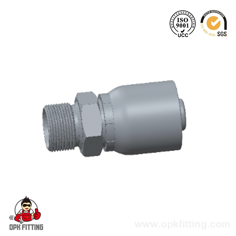
1. Raw Material: Carbon Steel & Stainless Steel available2. Standard Plating: Trivalent Zinc Plating ( Cr3 / Chrome Free ), Silver & Yellow3. ...
See Details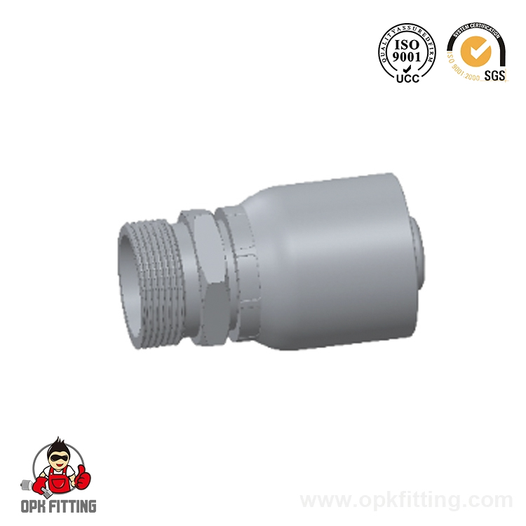
1. Raw Material: Carbon Steel & Stainless Steel available2. Standard Plating: Trivalent Zinc Plating ( Cr3 / Chrome Free ), Silver & Yellow3. ...
See Details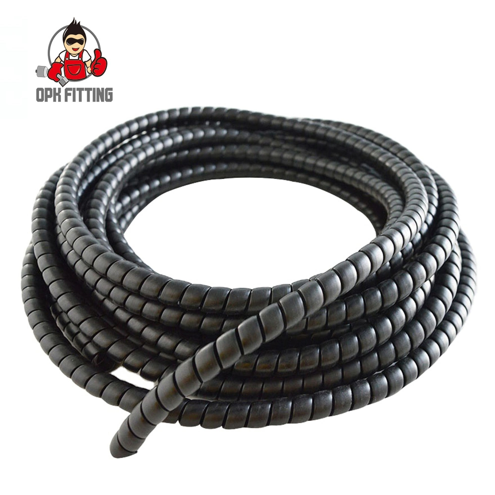
PRODUCT NAME: Spiral Protective Sleeve PP plastic hose guard for hydraulic hoseRecommended For: The use of Spiral Guard Wrap is an economical and conv...
See Details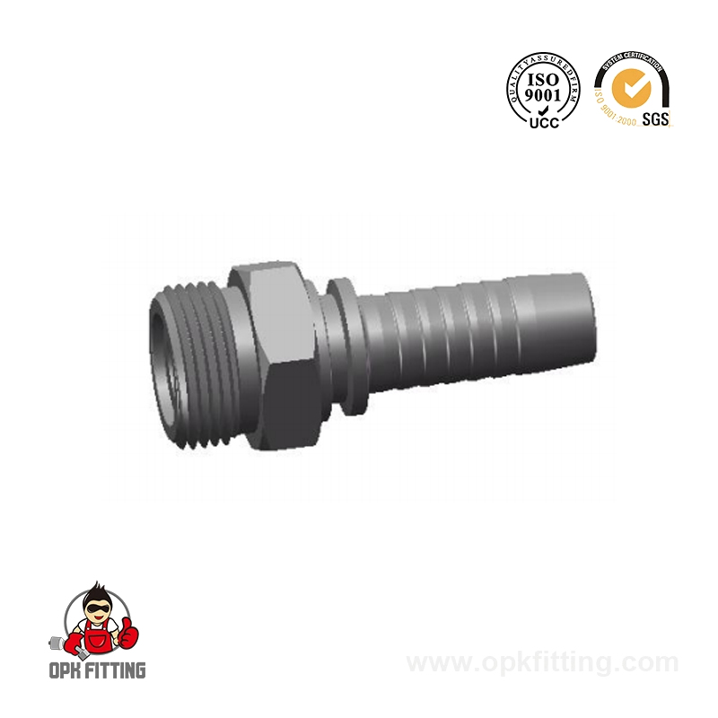
1. Raw Material: Carbon Steel & Stainless Steel available2. Standard Plating: Trivalent Zinc Plating ( Cr3 / Chrome Free ), Silver & Yellow3. ...
See Details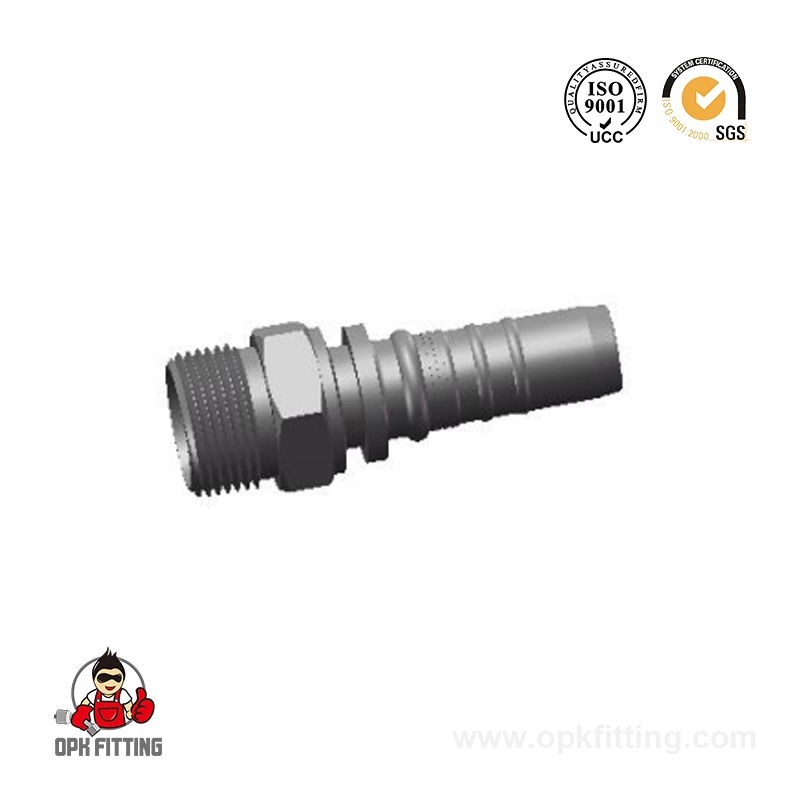
1. Raw Material: Carbon Steel & Stainless Steel available2. Standard Plating: Trivalent Zinc Plating ( Cr3 / Chrome Free ), Silver & Yellow3. ...
See Details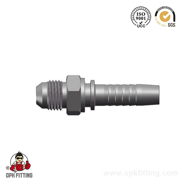
1. Raw Material: Carbon Steel & Stainless Steel available2. Standard Plating: Trivalent Zinc Plating ( Cr3 / Chrome Free ), Silver & Yellow3. ...
See Details

+86-18868902802


No. 298, Chenghai Road, Binhai New District, Fenghua Economic Development Zone, Fenghua District, Ningbo City, Zhejiang Province, China
Copyright @ Ningbo Opk Fitting Co., Ltd. Hydraulic Hose Fittings Manufacturers OEM & Custom Adaptors Company
