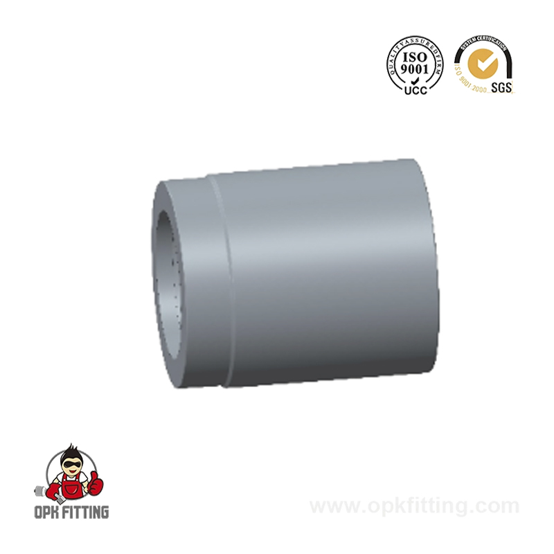
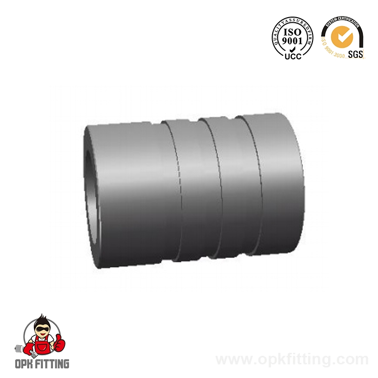
A hydraulic hose is a flexible, high-pressure conduit designed to transmit hydraulic fluid between components in a hydraulic power system. In plain terms: it is the critical link between a pump, control valve, cylinder, and motor that makes industrial machinery move. Without a properly specified hydraulic hose assembly, pressurized fluid cannot be directed, controlled, or delivered — and the machine stops working. Understanding what hydraulic hoses are, how they are built, and how to select the right one is therefore fundamental for anyone operating, maintaining, or procuring equipment in manufacturing, construction, agriculture, or any fluid-power industry.
The global hydraulic hose market was valued at approximately USD 1.8 billion in 2023 and is projected to grow steadily through the 2030s, driven by expanding construction infrastructure, agricultural mechanization, and industrial automation (Source: Grand View Research, 2024). This growth reflects the central role hydraulic hoses play in virtually every sector that relies on fluid power — from excavators and tractors to offshore platforms and medical equipment. As a specialist hydraulic hose manufacturer OEM and high pressure hydraulic hose supplier China factory with over a decade of production experience, the following guide is written to give beginners a thorough, practical foundation.
Table 1: Hydraulic Hose Quick Reference — Key Parameters at a Glance
Parameter
Typical Range
Notes
Working Pressure
35 – 420 bar (500 – 6,000 psi)
Depends on layer count and wire braid type
Bore Sizes (ID)
3/16" – 2" (4.8 mm – 51 mm)
Standardized per SAE J517 dash sizes
Temperature Range
-40°C to +125°C (standard)
Specialty compounds rated to +150°C
Minimum Bend Radius
25 mm – 300 mm
Critical: never bend tighter than specification
Common Reinforcement
1–6 wire braid / spiral layers
More layers = higher pressure rating
Key Standards
SAE J517, ISO 1436, DIN EN 853/856
Determines dimensions and test requirements
The Three-Layer Structure of a Hydraulic Hose
Every hydraulic rubber hose, regardless of pressure rating or application, is built around the same fundamental three-layer architecture. Each layer has a distinct engineering function, and the quality of materials and manufacturing at each layer directly determines how long and reliably the hose will perform in service.
Layer 1 — Inner Tube
The inner tube is in direct contact with the hydraulic fluid at all times and must be chemically compatible with it. Materials include Nitrile (NBR) rubber for petroleum-based mineral oils (the most common choice), EPDM for phosphate ester fire-resistant fluids, Neoprene (CR) for water-glycol fluids, and PTFE (Teflon) for the most aggressive chemicals and high-temperature applications. Selecting the wrong inner tube material causes rapid swelling, hardening, or delamination — and subsequent hose failure. Typical inner tube wall thickness ranges from 1.5 mm to 4 mm depending on bore diameter.
Layer 2 — Reinforcement
The reinforcement layer is what gives a high pressure hydraulic hose its pressure-carrying capacity. It consists of high-tensile steel wire wound or braided over the inner tube in one or more layers. Wire braid reinforcement (SAE 100R1, R2) uses individual wires woven in a crisscross pattern and suits working pressures up to approximately 250 bar. Wire spiral reinforcement (SAE 100R9, R12, R13) consists of multiple layers of helically wound wire — each layer wound in alternating directions — and achieves working pressures from 350 to over 420 bar. The number of reinforcement layers (1-wire braid, 2-wire braid, 4-spiral, 6-spiral) is the primary determinant of the hose's pressure rating.
Layer 3 — Outer Cover
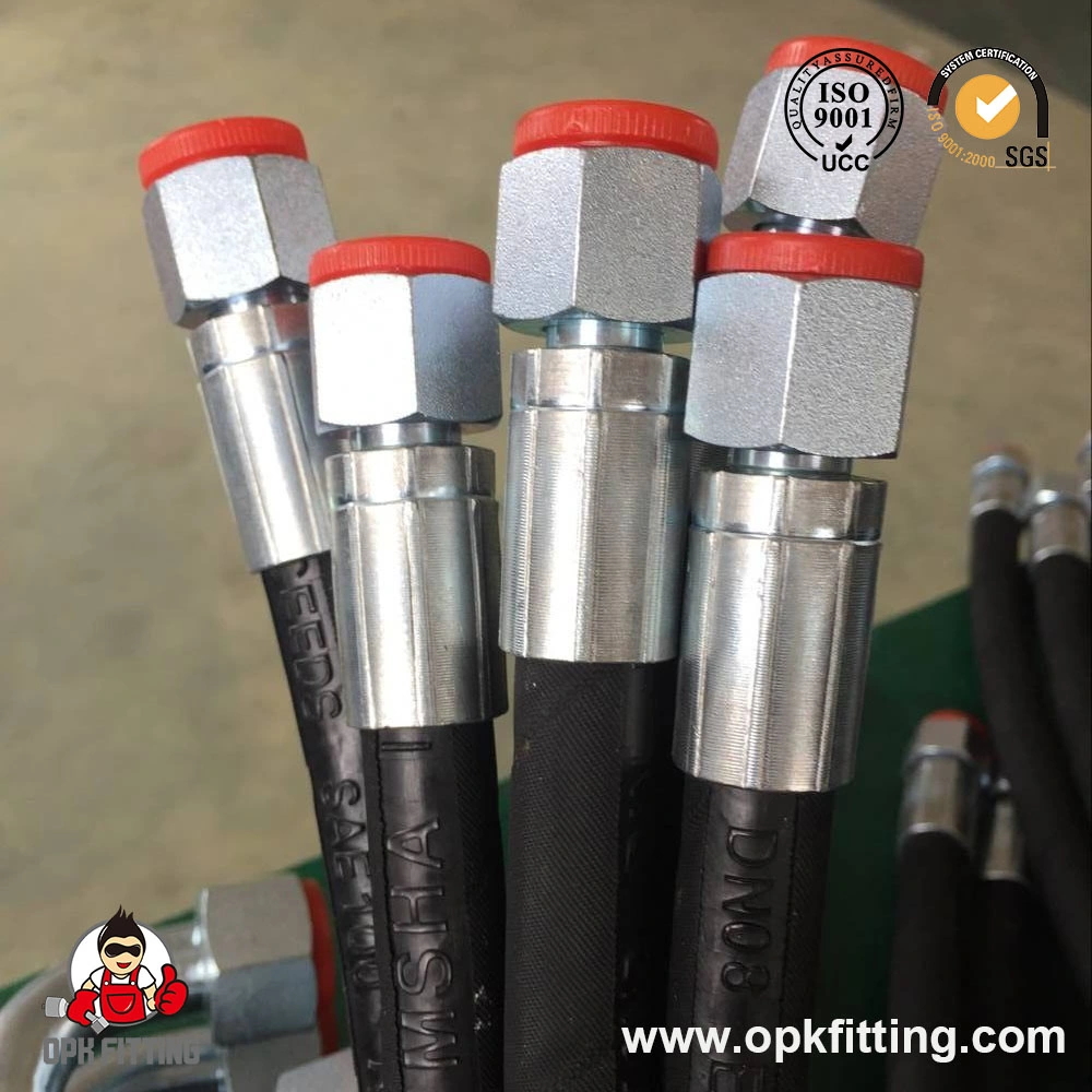
The outer cover protects the reinforcement from mechanical damage, abrasion, UV radiation, ozone, and fluid spillage. Standard cover materials are Neoprene or SBR rubber, providing good abrasion resistance in typical industrial environments. For extra-abrasion-resistant applications (mining, forestry, steel mills), a harder nylon or polyurethane braid cover is specified. Smooth-bore covers are easier to clean; wrapped-finish covers (showing a textile imprint) provide better grip during assembly. The outer cover should show the hose standard marking, manufacturer code, date of manufacture, and pressure rating in permanent ink — this information is essential for traceability and replacement specification.
Types of Hydraulic Hoses: SAE Standards Explained
The Society of Automotive Engineers (SAE) J517 standard is the most widely referenced classification system for industrial hydraulic hose types. Each SAE designation (100R1 through 100R17+) specifies inner tube material, reinforcement construction, cover type, pressure rating, and test requirements. Understanding these designations is fundamental when sourcing a hydraulic hose assembly supplier or specifying replacements.
Table 2: Common SAE Hydraulic Hose Types and Their Applications
SAE Type
Reinforcement
Max WP (1" ID)
Typical Use
SAE 100R1
1 wire braid
88 bar (1,275 psi)
General hydraulic lines, mobile equipment
SAE 100R2
2 wire braid
160 bar (2,325 psi)
Medium-pressure hydraulic systems
SAE 100R9
4 wire spiral
350 bar (5,075 psi)
High-pressure presses, excavators
SAE 100R12
4 wire spiral (heavy)
420 bar (6,090 psi)
Very high-pressure industrial applications
SAE 100R14
PTFE (braided SS)
207 bar (3,000 psi)
Chemicals, high temp, food/pharma
SAE 100R17
1 wire braid (compact)
280 bar (4,060 psi)
Compact machinery, tight routing
The bar chart illustrates how maximum working pressure increases dramatically from single wire braid (SAE 100R1, 88 bar) to four-spiral constructions (SAE 100R12, 420 bar). This nearly 5× pressure range across standard SAE types means that choosing the correct specification is not a matter of preference but of engineering necessity. An under-specified hose — for example, using an R1 hose in an R9 application — poses a serious burst risk, while an over-specified hose adds unnecessary weight, stiffness, and cost to the system. When sourcing from an industrial hydraulic hose exporter, always request the hose marking on the outside cover to verify the correct standard has been manufactured. ISO 1436 (equivalent to SAE 100R1/R2) and DIN EN 853/856 are widely used in European and international specifications and are interchangeable with their SAE counterparts for most practical purposes.
Hydraulic Hose Fittings: Types, Standards, and Selection
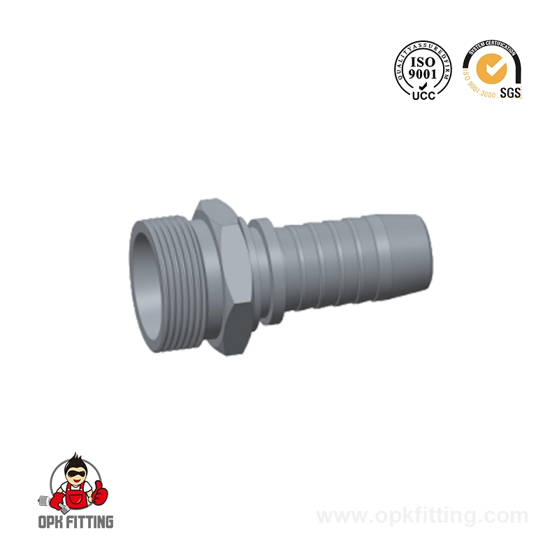
A hydraulic hose assembly is only as reliable as its end connections. Hydraulic hose fittings — also called hydraulic fittings or end connections — are the metal components crimped or swaged onto each end of the hose to connect it to ports, valves, cylinders, or other hoses. The fitting must withstand the same working pressure as the hose and form a leak-free seal under repeated pressure cycling, vibration, and thermal expansion.
Common Hydraulic Fitting Thread and Connection Types
BSP (British Standard Pipe): The most common thread type globally outside North America. Parallel (BSPP) and tapered (BSPT) variants. Sealing via a bonded washer (BSPP) or thread engagement (BSPT).
NPT / NPTF (National Pipe Taper): Dominant in North American markets. Tapered thread creates a metal-to-metal seal with thread sealant (PTFE tape or anaerobic compound). NPTF (Dryseal) provides a tighter fit without sealant.
JIC 37° Flare (SAE J514): A 37-degree flared seat on both the fitting and the port/tubing end. Widely used in North American mobile hydraulics. Reliable metal-to-metal seal, easy to reassemble multiple times.
ORB (O-Ring Boss, SAE J1926): Straight thread with a machined seating surface and an elastomeric O-ring. Excellent leak resistance under high pressure and vibration. Standard on SAE porting for mobile and industrial equipment.
ORFS (O-Ring Face Seal, SAE J1453): Flat-face fitting with O-ring seated in a groove machined into the fitting face. The most leak-resistant hydraulic connection type — required in sensitive environmental or fire-risk installations. Increasingly specified as default in new system designs.
DIN / Metric Fittings (24° Cone, DIN 2353): European standard using a 24-degree cone seat. Available in light (LL/L) and heavy (S) series. Widely used in German-manufactured industrial machinery and construction equipment.
Flanged Connections (SAE J518, Code 61/62): Four-bolt flange connections for very large bore (1" and above) high-pressure lines. Code 61 up to 210 bar; Code 62 up to 420 bar. Eliminating thread engagement entirely, flanges are the preferred connection for the highest-pressure applications.
As a professional hydraulic hose fittings manufacturer OEM and hydraulic hose fittings supplier China factory, our range covers all major thread standards in carbon steel, stainless steel 304/316, and brass, with plating options including zinc, nickel, and chrome. All fittings are dimensionally verified against the applicable standard and pressure-tested before dispatch.
The radar chart compares three of the most common hydraulic fitting connection types — ORFS, JIC 37°, and BSP — across five practical selection criteria. ORFS fittings score highest for leak resistance, making them the preferred choice for high-pressure systems or installations in environmentally sensitive locations where any fluid leakage is unacceptable. JIC fittings offer an excellent balance of pressure rating and reusability, explaining their continued dominance in North American mobile and agricultural equipment. BSP fittings, while slightly lower in peak pressure and leak resistance, benefit from unrivaled global availability and are the default specification across European, Asian, and Australian industrial markets. When specifying hydraulic fittings, always confirm the thread standard from the port or equipment manual before ordering — mixing incompatible thread types is a leading cause of fitting failure and hydraulic leaks in field installations.
Where Are Industrial Hydraulic Hoses Used? Key Application Sectors
Industrial hydraulic hose assemblies are deployed across virtually every sector of the modern economy. The common thread: wherever a machine needs to generate controlled force, movement, or torque through fluid power, a hydraulic hose assembly is the conduit that makes it possible. Below are the primary application sectors with specific use cases.
Construction & Civil Engineering: Excavators, bulldozers, cranes, concrete pumps, and road rollers all rely on high-pressure hydraulic hose assemblies for boom movement, bucket actuation, and stabilizer control. SAE 100R9 and R12 spiral hoses are standard for excavator arm and bucket circuits operating at 350–420 bar.
Agriculture: Tractors, combine harvesters, and self-propelled sprayers use hydraulic hoses for steering, lifting, and implement control. Agricultural hydraulic circuits typically operate at 200–280 bar, with SAE 100R2 or R17 being common specifications. Flexibility and low-temperature performance are critical for outdoor operation.
Manufacturing & Metal Processing: Hydraulic presses, injection molding machines, die-casting equipment, and steel rolling mills use ultra-high-pressure hose assemblies. SAE 100R12 spiral hoses rated to 420 bar serve press circuits, while industrial robotic arms use compact-profile hoses to maintain flexibility within tight cable carriers.
Offshore & Marine: Subsea equipment, ship steering gear, crane hoist systems, and ROV (Remotely Operated Vehicle) umbilicals require hydraulic hoses with enhanced resistance to saltwater, UV radiation, and low temperatures. PTFE-lined or stainless-steel-braided hoses are specified for the most demanding marine environments.
Petroleum & Gas: Wellhead control panels, blowout preventers (BOPs), and pipeline tools require flame-resistant hydraulic hose assemblies meeting API and ABS/Lloyd's Register approvals. Fire-resistant fluid compatibility (typically phosphate ester or water-glycol) governs inner tube material selection in this sector.
Pharmaceutical & Food Processing: Sanitary hydraulic hoses with FDA-compliant inner tube materials and stainless-steel fittings convey food-grade hydraulic fluids in presses, conveyors, and processing equipment where contamination of the product must be prevented.
Construction accounts for the largest share of global hydraulic hose demand at approximately 32%, driven by the global infrastructure investment cycle and the widespread adoption of hydraulic excavators and lifting equipment in developing economies. Agriculture follows at 22%, supported by growing mechanization in Asia, South America, and Africa. Together, these two sectors represent more than half of all industrial hydraulic hose consumption worldwide. The petroleum and marine sectors, while smaller in volume, drive demand for premium-specification hoses — PTFE-lined, stainless-braided, and fire-resistant types — which carry significantly higher engineering and manufacturing complexity than standard rubber hoses. Companies choosing to buy hydraulic hose wholesale for construction or agricultural applications benefit from the widest selection and most competitive sourcing, while offshore and chemical process customers require closer technical collaboration with their industrial hydraulic hose assembly supplier.
Why Hydraulic Hoses Fail: Top 6 Causes and How to Prevent Them
Understanding failure modes is as important as understanding hose construction. Studies from fluid power industry bodies consistently show that over 80% of hydraulic hose failures are preventable with correct specification, installation, and maintenance practices. The following are the six most common failure causes identified in field investigations.
Incorrect Hose Routing (Mechanical Damage): Hoses routed too tightly — below the minimum bend radius — experience internal wire fatigue at the bend point. Over time, wires fracture, the hose loses pressure capacity, and eventually leaks or bursts. Always follow the manufacturer's minimum bend radius specification; for most 3/4" hoses this is 100–150 mm.
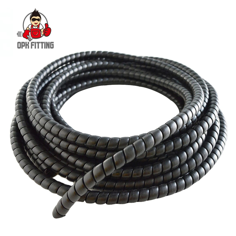
External Abrasion: Hoses rubbing against sharp metal edges, other hoses, or structural members abrade the outer cover, expose the reinforcement, and accelerate corrosion. Use abrasion-resistant covers, plastic spiral guards, or P-clamps to create clearance between hose runs.
Fluid Incompatibility: Using a hose with the wrong inner tube material for the hydraulic fluid causes the tube to swell, harden, or delaminate. Always confirm fluid compatibility — particularly when switching from mineral oil to synthetic or fire-resistant fluids.
Pressure Surges (Impulse Fatigue): Rapid opening and closing of directional control valves creates pressure spikes that can momentarily exceed rated working pressure by 2–4×. Over thousands of cycles, these impulses cause wire reinforcement fatigue. Specify spiral-reinforced hoses for high-cycle applications; braid-reinforced hoses are less tolerant of repetitive impulse loading.
Incorrect Fitting Crimping: An under-crimped or over-crimped fitting does not grip the hose correctly. Under-crimping allows the hose to blow off the fitting under pressure; over-crimping cuts into the inner tube and creates a stress concentration. Always crimp using the fitting manufacturer's specified die and crimp diameter — never estimate by feel.
Age and Environmental Degradation: Rubber compounds oxidize, ozone-crack, and harden over time even without mechanical damage. Industry guidance (ISO 6945 and SAE J1273) recommends a maximum storage life of four years from manufacture date and a maximum service life of six years in normal industrial service, regardless of visual condition. Always check the hose manufacture date (printed on the cover) when replacing assemblies.
The line chart above illustrates how the relative failure rate of a hydraulic hose in normal industrial service remains relatively stable for the first three years and then rises sharply after year four — the threshold at which SAE J1273 and ISO 6945 recommend replacement regardless of visual appearance. The curve highlights why a reactive maintenance approach (replacing hoses only when they leak) is far more costly than a proactive scheduled replacement program: a failed hose in service causes hydraulic fluid contamination, downtime, potential fire risk, and injury hazard, all of which carry costs far exceeding the hose itself. Field studies have shown that organizations implementing a 4-year maximum service-life policy for high pressure hydraulic hose assemblies reduce unplanned hydraulic downtime by 40–60% compared to condition-based-only maintenance approaches (Source: Parker Hannifin Hose Products Division Technical Data, 2022).
How to Correctly Size a Hydraulic Hose: The STAMPED Method
The industry-standard method for correctly specifying a hydraulic hose assembly is the STAMPED acronym, originally developed by Parker Hannifin and now widely adopted across the fluid power industry. Each letter represents a critical parameter that must be confirmed before selecting or manufacturing a hose assembly.
Table 3: The STAMPED Method for Hydraulic Hose Specification
Letter
Parameter
What to Specify
S
Size
Inside diameter (ID) based on flow rate and velocity target (2–4 m/s for pressure lines; 1–2 m/s for return lines)
T
Temperature
Min and max fluid temperature AND ambient temperature at the hose routing location
A
Application
Static or dynamic (flexing) use; routing constraints; proximity to heat sources or sharp edges
M
Material / Media
Hydraulic fluid type (mineral oil, phosphate ester, water-glycol, vegetable oil) for inner tube compatibility
P
Pressure
Maximum continuous working pressure AND peak surge pressure. Hose working pressure rating must exceed peak surge.
E
Ends / Fittings
Thread type, size, and orientation (straight, 45°, 90° elbow) for each end of the assembly
D
Delivery / Length
Overall assembly length (center-to-face or face-to-face), accounting for 10–15% length change under pressure
When working with an industrial hydraulic hose assembly supplier or submitting an OEM specification to a hydraulic hose manufacturer OEM, providing all seven STAMPED parameters at the outset eliminates the most common sources of misspecification. A particularly critical — and frequently overlooked — parameter is hose ID selection based on flow velocity. Using a hose ID that is too small creates excessive fluid velocity, generating heat, pressure drop, and erosion of the inner tube. The target velocity in hydraulic pressure lines is 2–4 m/s; for suction and return lines, 1–2 m/s. Given a flow rate Q (L/min), the correct ID can be calculated as: ID (mm) = 4.6 × √(Q / v), where v is the target velocity in m/s.
About OPK FITTING Hydraulic Equipment Factory
OPK FITTING Hydraulic Equipment Factory is a China-based professional manufacturer specializing in hydraulic hose fittings, hydraulic adapters, and complete hydraulic hose assemblies. With over 10 years of production experience and a team of skilled design engineers, OPK serves customers in machinery, metallurgy, petroleum, construction, marine, aerospace, agriculture, pharmaceutical, and food processing industries globally.
Our manufacturing scope covers all major pressure levels from low-pressure return-line hoses to high pressure hydraulic hose assemblies rated above 400 bar, across a full range of flexible hose types, fitting thread standards (BSP, NPT, JIC, ORFS, DIN metric, SAE flanges), and materials (carbon steel, stainless steel 304/316, brass). We provide comprehensive ODM/OEM customization services for hydraulic fittings and hydraulic pipe assemblies, ensuring full dimensional compliance with customer drawings and applicable standards (SAE, ISO, DIN). Product quality is supported by full material certifications and pressure testing records on every manufactured batch.
As a direct-source hydraulic hose fittings supplier China factory, OPK offers single-item and wholesale supply, with flexible MOQ policies for both standard catalogue items and custom-engineered assemblies. Our customer service team provides pre-sales technical support, sample evaluation, and ongoing order management — making OPK a reliable long-term partner for buyers seeking to buy hydraulic hose wholesale or establish an OEM supply arrangement for hydraulic components.
Frequently Asked Questions About Hydraulic Hoses
Q1
What is a hydraulic hose used for?
A hydraulic hose transmits pressurized hydraulic fluid between components in a hydraulic system — connecting pumps, valves, cylinders, and motors. It provides flexible routing in applications where rigid tubing cannot accommodate movement, vibration, or machine articulation.
Q2
How do hydraulic hose fittings work?
Hydraulic hose fittings are crimped or swaged onto each end of the hose using a hydraulic crimping machine. The fitting collar compresses around the hose outer cover, gripping the reinforcement and creating a mechanical lock between the fitting body and the hose. The fitting thread then connects to a port or valve, completing the circuit with a pressure-tight seal.
Q3
What are the types of hydraulic fittings?
The main types include BSP (British Standard Pipe), NPT/NPTF (National Pipe Taper), JIC 37° Flare, ORB (O-Ring Boss), ORFS (O-Ring Face Seal), DIN 24° metric, and SAE four-bolt flanges. Selection depends on the equipment port standard, working pressure, and fluid type.
Q4
Why do hydraulic hoses fail?
The most common causes are: routing below the minimum bend radius (wire fatigue), external abrasion (cover wear exposing reinforcement), fluid incompatibility with the inner tube, pressure surges exceeding the rated working pressure, incorrect fitting crimp, and natural aging beyond the 4–6 year recommended service life.
Q5
How do I choose the right hydraulic hose size?
Size the hose ID based on your system flow rate and target fluid velocity (2–4 m/s for pressure lines). Use the formula: ID (mm) = 4.6 × √(Q / v), where Q is flow in L/min and v is velocity in m/s. Then select the hose type (SAE standard) with a working pressure rating exceeding your system peak pressure by a safety margin.
Q6
What is the SAE standard in hydraulic hoses?
SAE J517 is the Society of Automotive Engineers standard that classifies hydraulic hoses as SAE 100R1 through R17+. Each designation defines the hose's construction (reinforcement layers, tube and cover materials) and performance requirements including working pressure, burst pressure, bend radius, and impulse cycles. SAE standards are used worldwide as a common design and procurement language for hydraulic hose specifications.
Q7
How often should hydraulic hoses be replaced?
Per ISO 6945 and SAE J1273, hydraulic hoses should be replaced after a maximum of 6 years in service (with many manufacturers and OEMs recommending 4 years for high-pressure or high-cycle applications), regardless of visual appearance. The manufacture date is printed on the hose cover. Hoses showing cracks, blistering, cover damage, or fitting leakage should be replaced immediately.
Q8
What causes hydraulic hose leaks?
Hydraulic hose leaks originate at three points: the fitting-to-port connection (caused by incorrect thread torque, damaged sealing faces, or missing O-rings), the hose-to-fitting interface (caused by incorrect crimp diameter or fitting pull-off failure), or through the hose wall itself (caused by pinhole erosion, cover damage exposing corroded reinforcement, or inner tube delamination from fluid incompatibility).
PRODUCT NAME: Spiral Protective Sleeve PP plastic hose guard for hydraulic hoseRecommended For: The use of Spiral Guard Wrap is an economical and conv...